Introduction
This is a work in progress. The system has been in use for over a year it all works but I expect to get all details online soon.Described here is a complete chip system intended for timing running races.
With minor changes it can be modified to cope with cycling or triathlons or many other race types.
Unlike other online chip timing guides, which tend to leave out a lot of the important details, this one includes everything needed, including software, to create a working chip timing system.
If you find some detail is missing, get in touch and I'll include it.
Software is included to operate the chip reader allowing chips to be read, processed and converted into results for importing into whatever results program you have.
In its basic version, as shown below, the results will appear as a .csv file with each line in the file giving the race number and time of the runner in that position.
This CSV file can be cut&pasted into a spreadsheet or imported into whatever results program you prefer.
As an example, here is the chip timer output file produced for this race.
Time is formatted as MMSS so 1234 means 12m34s.
The simplest version of the chip timing system is very cheap and can be built for under Ł1000. Most of that, about Ł700, is for the chip reader itself.
You then need antennae, tripods, cables and connectors, a laptop/tablet PC, a power supply (battery) and a box to put it in to keep the weather out.
Optionally, you can add a camera as a backup.
What's described is the system designed for the North East Harrier League during 2016.
This is a cross country league in the North East of England, run over 7 meetings during winter.
Each meeting has 10 races covering male and female, under 11 to senior, and each race consists of 30 to 600 runners.
A total of 1200-1500 runners take part at each meeting.
The races are handicapped so runners tend to finish more bunched than in a normal race of similar distance. The peak finish rate of the largest race is around 90 runners per minute and the system copes well with that.
You can see the typical results from a single meeting here.
The system was introduced into the league as the main timing system in early 2017 to replace the usual manually recorded and timed results.
It has worked very well since then removing the need for 16 officials and 3 race admin and getting results online within minutes of the race finishing, sometimes during the race.
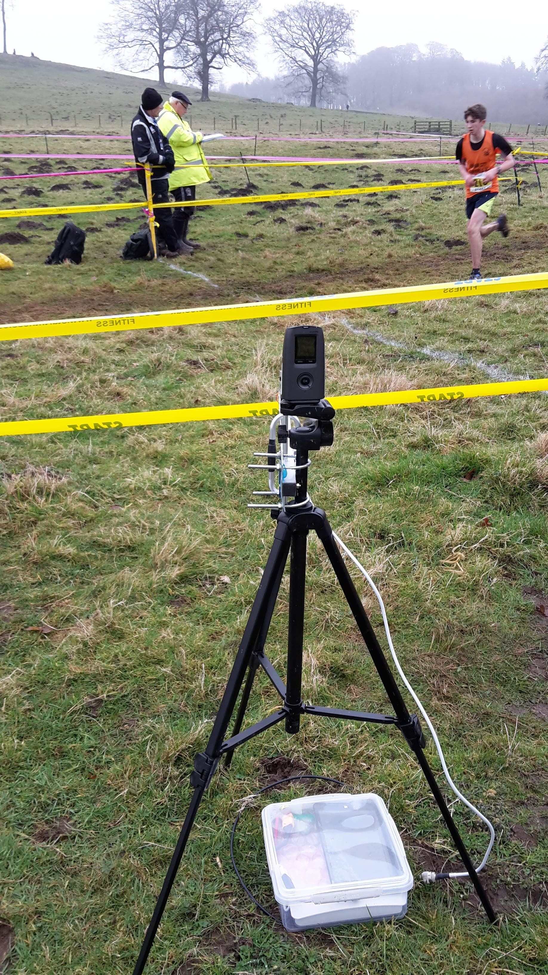
This picture shows an entire 1 antenna chip reader in use at the finish line of a cross country race.
There is a camera mounted on the tripod as backup and the chip reader, battery and tablet PC driving the chip reader are in the white box. Click the image for a larger picture.
For the cross country I set up 3 of these, one on the finish line as shown here, with a slightly larger antenna, and 2 in a short finish funnel.
The one on the finish line catches 99.5% of finishers but they are then directed into the finish funnel where they pass within 1m of another reader which catches 100% (other than the odd dud chip).
The third reader is redundant and is purely for backup.
Main components
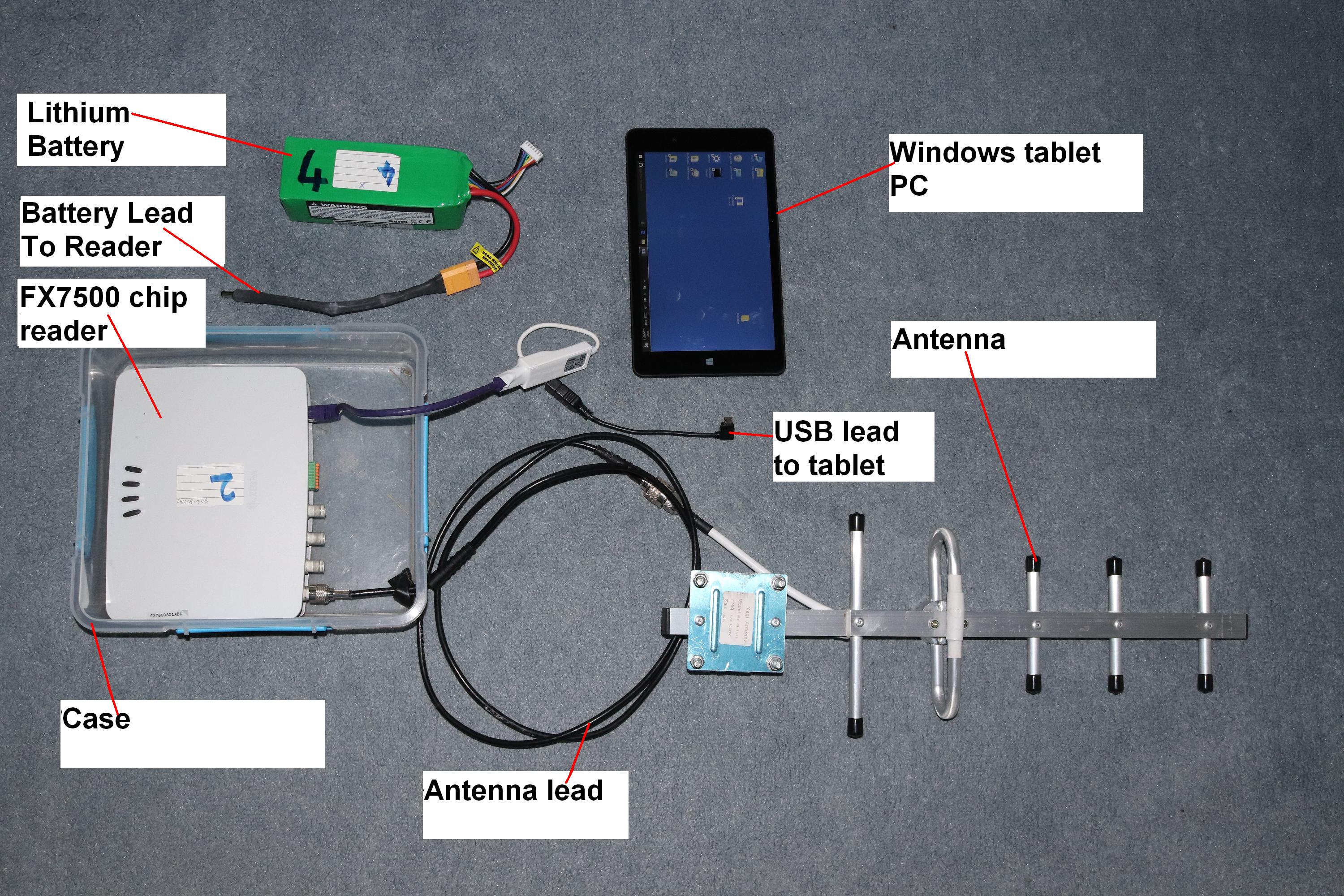
To show how little you need to make a working chip timer, here is a view of a single antenna chip timer opened out from its case and labelled.The only addition you need is a tripod to mount the antenna on and an optional camera as backup, which would be mounted on the same tripod. Click the image for a closer view.
This reader has 4 antenna ports so can operate up to 4 antennae, but as explained later, 1 antenna will often do a better job.
Some versions of the reader have 2 antenna ports and other readers have up to 8 antenna ports, but you won't need that many.
The tablet shown will run for 6 hours from its own internal battery and the Lithium battery shown will run the chip reader for 10 hours so the system can be setup before the meeting and be left unattended for the meeting duration, which is about 4 hours for this particular cross country.
Overview
Most race chip timing systems are based on EPC Class1 Gen2 compliant readers and tags. That's what will be described here.These systems were not designed for race timing, they are intended for logistics and are installed all over the world to track goods in and out of warehouses, trucks and ships so they are well established and not too expensive.
These are UHF systems and operate at frequencies around 860-960MHz. The exact frequency range varies from country to country and you will often need to set up the reader to use the correct frequencies before timing races with it.
The RFID tags for these systems are made by the million and are very cheap. If you buy a full reel of 5000 chips, which is the basic minimum order quantity, they cost around Ł600 which is around Ł0.12 per tag so they can be treated as disposable, just as bibs are.
This saves a lot of hassle trying to collect chips in after races.
A very common tag used in race timing is the Smartrac Dogbone tag and, after testing a few different tags I found them to be the best so that's what is described here.
A bottom of the range, fully functional chip timing system needs just the items listed above, plus a few stakes/cones and some tape to mark out the finish area and a good, enthusiastic operator.
Or you may prefer to go big and have finish gantries, inflatable arches, multi point timing around the course, big clocks and on the day registration setups and a truck to carry all the equipment to races.
The choice is yours but my choice was dictated by the need to carry all the equipment by hand to remote cross country locations so small, light and minimalist was best.
If you're selling your race timing services then some race organisers may be impressed with arches and flags, large clocks and overhead gantries so you may be able to charge more for your services.
I will first describe the simplest hardware setup and later explain how to extend this to more complicated systems.
Ability to cut cables and attach connectors is assumed. You can buy ready made cables but DIY is a lot cheaper and is a useful skill to have when someone trips over a cable and you need to repair it in a hurry.
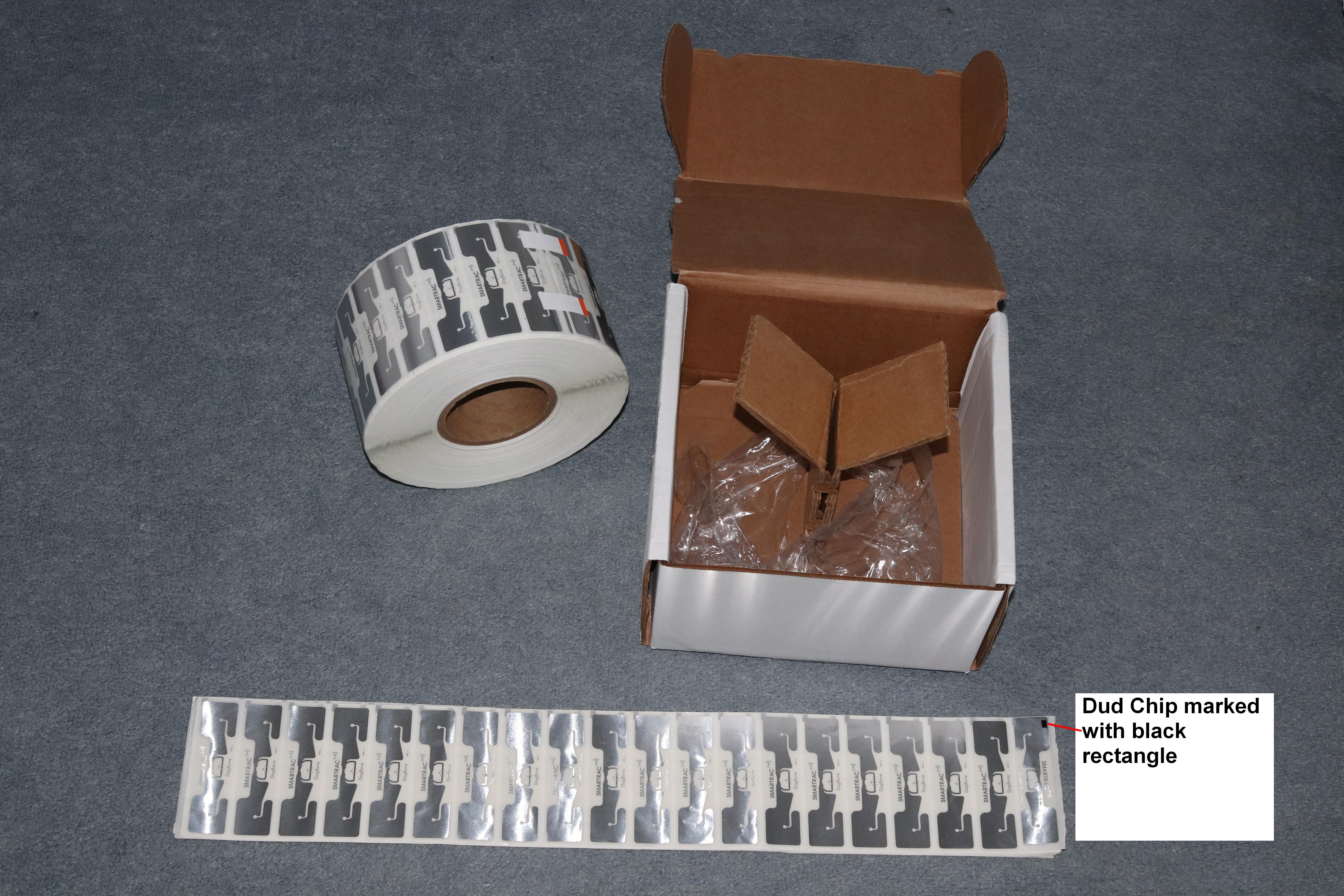
If bought in bulk, the chips come on reels of 5000 weighing 3kg.
If bought in smaller quantities then someone has split the reel and counted off as many chips as you need, and they will usually be supplied in strips as shown.
Note that not all 5000 chips on a reel are perfect. A small number will fail quality checks and they are marked with a black rectangle on the front, as shown in the picture. Click the picture to see a larger version.
These marked chips should not be used.
Component details
Here are the details as used for the North East Harrier League system.A lot of these can be varied to suit your own setup.
The chip reader
This is the most expensive component in the system.The reader used here is the Zebra (formerly Motorola) FX7500.
It is available in a number of variants depending on location and the number of antennae you want to use.
This specific one is part number FX7500-42325A50-WR
Variants include:
FX7500-42320A50-US: 4-Port FCC
FX7500-22320A50-US: 2-Port FCC
FX7500-42325A50-WR: 4-Port Worldwide
FX7500-22325A50-WR: 2-Port Worldwide
All this type of RFID chip reader operate in a frequency range of 860-960MHz and each country has its own particular frequencies within that range.
FCC readers are only suitable for use in the USA and compatible countries. The Worldwide readers need a little setting up to select the frequency for your particular location.
They'll all work with this project.
TheFX7500 chip reader costs about Ł700. Be aware that sometimes they come with a power supply and sometimes the power supply is extra.
The system described here doesn't use the power supply as the cross country courses have no mains power, so batteries must be used, but, if you're planning on powering your system with the mains, make sure your reader includes the power supply.
A reader power supply can come in useful for testing, setting up and allocating chips to runners so, even if you intend using batteries for races, it might be worth having at least one power supply.
The power supply
If you intend powering the chip reader for the mains then you'll need to get the power supply. These are 24V 3A supplies although the reader consumes under 1A.The company your buy the chip reader from should also supply the power supply and it's sometimes included in the price of the chip reader, but not always.
The alternative is battery power and that's what's used in this project.
The chip readers are specified for 24V but will work down to 12V. Lead acid batteries are available at 12V each so you could use a 12V lead acid battery but they weigh a lot!
A better solution, if weight is an issue, is to use a Lithium polymer (LiPo) battery. These come is 3.7V increments so a 4 cell LiPo would be 4x3.7V = 14.8V which would be adequate.
I found the best compromise of voltage, price and capacity to be a 6 cell LiPo with a voltage of 6x3.7 = 22.2V but if you find a good offer on 4 cell batteries then they might be a better buy.
I settled on this one: https://hobbyking.com/en_us/multistar-high-capacity-6s-6600mah-multi-rotor-lipo-pack.html
and if you wait for the right offer you can get them for under Ł30 each.
This battery will power a FX7500 reader non-stop for well over 10 hours on a single charge.
You will need to get a LiPo battery charger as they need special chargers. Search for a suitable one on the same website.
This battery weighs about 850g. The equivalent capacity Lead Acid battery will weigh about 2.2kg.
As pointed out later, I often use 3 chip timing units for extra redundancy so the total saving in weight using LiPo batteries instead of Lead Acid is 3.8kg which is a considerable weight saving when carrying the equipment in a holdall a mile across muddy fields.
Battery capacity needs to be enough to power the chip reader for the duration of your competition.
For some races, such as a 5k, this will just be 30-60 minutes to cover the time taken for all the finishers to cross the finish line. For other races, such as a marathon, finishers can take from 2 to 6 hours so the battery will need to last at least 4 hours.
I include a 50% extra capacity as the batteries will deteriorate with age so 50% over capacity now will ensure the batteries are still good enough in 10 years time to last the duration.
To calculate the required battery capacity, for the FX7500 used here, assume about 15Wh of battery capacity per hour of use.
Watt-Hours (Wh) is the product of the battery capacity in Amp-hours(Ah) and the nominal battery voltage.
The battery used here is a 6600mAh (=6.6Ah) capacity 22.2V battery which gives 6.6x22.2 = 146Wh.
That will last about 146/15 = 9.5 hours which is plenty of spare capacity for my event which lasts 5 hours maximum.
The computer
Just about any Windows laptop or Windows tablet PC can be used. I used the cheapest I could get.There are 2 variants in use, a Linx 810 and a Viglen Connect NXR08001. These are both 8 inch tablets running Windows 10.
The tablets are good for this setup because they are very light and small enough to be packed in a tiny box with the reader but the reader and the software will work with just about any Windows computer. It has been run on a 7inch netbook with WinXP and a bottom of the range Win7 laptop (HP 15-r101na) was used to simultaneously run 2 readers with no problems.
In use, the chip reader software uses less than 2% of the tablet's resources and, although I haven't tried it, there is no reason 1 laptop can't be used to run as many chip readers as you can network it to.
Chip reading is actually not a computer intensive task at all, the difficult work takes place within the reader.
The cables
The USB port and Ethernet port use standard cables you should be familiar with. Just buy cables that are the right length as long ones can get caught or tangled when setting up the equipment.
Antenna cables are more complicated.
Chip readers use UHF frequencies, similar to TV, and long cables lose a lot of the signal.
If you're using a long cable run to the antenna then you will need to invest in low loss cable which gets very expensive and is also heavy, stiff and difficult to handle.
The system described here uses very short cables, of under 1 metre, so cable quality is not a problem and I can use the cheapest suitable cable available.
The "standard" cable is RG-58. This is cheap (Ł0.35/m), flexible and ok for short leads.
A better cable is CLF-200 but it costs a little more and is not quite so flexible.
Or you could try LMR-400 which is much better, but it'll cost you a lot, maybe Ł3.00 or more per metre.
The case
This is a matter of personal preference. Just choose something that matches your setup.In early tests I just used a holdall with a laptop and zipped it up if the weather looked bad, but a solid case of just the right size is much easier to handle and transport and affords some protection to the equipment.
Then I tried the much more compact children's lunch bags from Sainsburys which were just the right size but they aren't fully waterproof and I couldn't see what was going on without opening the bag.
Finally, I settled on is the Sistema 3.5l bakery box intended for food storage.
It was chosen because it was just big enough to hold my chosen components, it has a transparent lid so I can see the tablet screen without needing to open it and expose the insides to the weather, and it's waterproof.
I did need to cut a hole in for the antenna lead and that should be sealed with a rubber grommet of the correct size to keep out rain.
The antennae
There's a lot of variety here.The first choice is to use timing mats on the ground or not.
If you decide not to use timing mats then the second choice is overhead gantries or antennae mounted to the side of the course.
Then there is antenna polarisation to consider.
UHF radio signals have trouble passing through people so, to get a good view of all the chips in a crowd of people, you need your antenna to be below or above the course so they can't be blocked, as side antenna will likely be blocked by other runners. This is a particular problem if you want a chipped start where runners are tightly packed.
Timing mats are good but they are bulky and expensive. The cost of a 6m long timing mat, suitable for most races, is still over Ł2500, just for the mat. That triples the cost of your timing system as the rest of the equipment is under Ł1000.
There's nothing special about timing mats, they are just a number of the same or similar panel antennae mentioned below, but they are encapsulated into a mat which can resist thousands of runners (maybe in cross country spikes) and the occasional car passing over them.
Your chip reader will need more than 1 antenna output to drive a mat. The mats have an antenna every 1 to 2m so you might need a 4 output chip reader to operate a 6m timing mat. Check before buying.
Overhead gantries are an alternative to mats. They are still expensive and heavy and they take time and space to set up but they can impress race organisers and you can mount adverts and clocks on them as well as the antennae.
Described here are side antennae. These are light, quick to deploy, cheap and functional but they don't handle crowds well so they'd struggle with a chip start.
The rest of the system is identical whether you use gantries, mats or side mounted antennae. They're all basically the same antennae, just packaged or mounted differently, so the same reader will work with any of them.
Finish layout
This is rarely discussed in connection with chip timing but it is crucial to understand how layout can affect results.
Timing mats tend to be the easiest. You lay them along the finish line, runners' feet will always pass within 50cm of an antenna so if you mount the chip on the ankle or shoe then you'll get good results.
But use a bib mounted chip and the chip is then about 1.5m away from the antenna and the detection zone spreads out to maybe 2m before the finish line adding maybe half a second error to each runner's time.
Overhead gantries are not quite so good.
To use foot mounted chips with an overhead gantry means every chip crosses the finish line about 3m away from the antenna so the chip is in view of the antenna maybe 5m ahead of the finish line and maybe a 1second timing error.
Using a bib mounted chip raises that by maybe 1.5m so it's now only 1.5m below the antenna, similar to a timing mat with bib mounted chip and with a similar 0.5s error.
Side mounted antennae suffer the most from this. A 6m finish line with the antenna on one side of the course will see chips maybe 8-10m before the finish, introducing a timing error of well over a second for those finishing on the far side of the course.
There are tricks to mitigate the problem. One will be described later.
Connectors
If you are using a battery to power the reader than you'll need a connector compatible with the reader.You can either cut off the battery connector and replace it with this one or you can make up a lead to convert one to the other.
Be careful of cutting off the battery connector as some LiPo battery chargers need the connector to re-charge the battery so you can't cut it off until you know your LiPo charger doesn't need it.
Other chargers (usually the less powerful ones) will charge the battery via the balance lead only (the white block connector on the battery) and won't need the main connector.
For the antennae cable you will need 2 connectors, one for each end.
The one needed for the reader is this one. Pack Of 10 N-Type Male Crimp Connector - RG58/CLF200
The one needed for the antenna end depends on the antenna you buy so you'll have to figure that one out yourself.
For Zebra panel antennae (and almost antennae sold as RFID antennae), this is what you need: this one.
For the Yagi antennae, you might be lucky to find one with the correct connector but, more likely, you'll have to cut off the supplied connector and attach a new one or maybe use an adapter.
Timing accuracy
Don't expect perfect timing from a chip timer!The main advantage of a chip timing system is that it removes the huge effort of manually recording race positions and times and typing them into a computer, along with all the usual errors and mistakes which take ages to fix afterwards.
A chip timer will do approximately as good a job at timing as a good manual timekeeper. This applies to all this type of chip timer, not just this one.
Expect times good to the second, but if you want accuracy to tenths of a second then you'll be disappointed.
Chip timing is no replacement for photofinish.
There are many causes for this lack of accuracy.
First, each chip reader can only operate 1 antenna at a time. If you have 4 antennae connected to a single chip reader than each antenna is switched on one at a time, looks for chips and is then switched off while the next antenna is powered up.
Typically, for the FX7500 chip reader, each antenna switches about every 120ms, so with 4 antennae, each antenna will be on for 120ms and off for 360ms before switching on again.
Also, each antenna takes about 100ms to get fully up to maximum sensitivity after a switch. As result, the timer can't possibly record to better than about 0.4s, although it will report the exact time it saw the chip to the microsecond, the time it saw the chip and the time the chip crossed the line are not the same thing.
Then there's the distance from the antenna of the chip being read.
No antenna gives a sharp field of view just along the finish line. The signal from any antenna will spread out as it moves further away from the antenna.
As a result, and antenna looking along the finish line will be able to see chips maybe 1m either side of the finish at 1m from the antenna, but will see chips 5m either side of the finish at 5m from the antenna. This 5m represents over 1 second for a moderate runner so you can see that exact timing is never possible.
A timing mat with ankle mounted chips will do a better job as the chips will always pass within 50cm of the antenna but that's still an error of more than 0.1s on top of the antenna multiplexing delay of 0.4s and there's also the timing error depending on which foot the runner crosses the line with first, the chipped foot or the non-chipped foot.
So you can see that even the best antenna layout is nowhere near accurate enough to give times to 0.1s and 1 second accuracy is probably a reasonable goal.
There are ways to mitigate some of these problems which will be described later, but you'll never eliminate them altogether.
Build a system
That's enough pre-amble. Let's build a chip timing system.For the initial test system you will need a chip reader, an antenna, a lead to connect the antenna with appropriate connectors on each end, a Windows computer, a power supply and some chips to test.
At this stage, you don't need tripod, case, or a purpose bought computer.
Here is the material I bought but you can buy whatever quantities you like from anywhere you choose. This is just for reference:
My original chip readers were Zebra FX7500-42325A50-WR
One was bought from Codegate in August 2016 for Ł672 (Including 20% VAT but not including delivery (Ł12?)
This one came with a power supply so it's worth contacting them for a price and to confirm if the power supply is still included.
I also got some from http://www.morecomputers.com in October 2016 for Ł674 inc VAT and Delivery but these came without a power supply.
Shop around for a good deal. Currently (June 2018) the cheapest I can find is a 2 port version (although the picture is a 4 port version!) from https://transparent-uk.com/zebra-fx7500-usb-white-rfid-reader-fx7500-22325a50-wr.html for Ł658 inc VAT (don't know if power supply is included) but you can often get bargains for second hand readers on E-bay for a lot less.
Any laptop or desktop computer will do for testing so you don't need to buy one new just yet.
The antennae I use are these:
For the finish line: http://cpc.farnell.com/lprs/yagi-869-914a/antenna-yagi-6-element-869-915mhz/dp/RF00377
For other locations (see later for a full description of the system I use): 5 element 900MHz Yagi antenna
It's difficult to tell what connector these will come with so be prepared to cut off the connector and replace it with something appropriate. It's a good idea to buy the antenna before buying the connectors and leads so you know what you'll need.
Often the antenna will have an SMA connector so you may prefer to use an adapter rather than cutting it off.
You may also wish to look at these panel antennae, depending on your intended setup, but they are more expensive.
Most chip timing companies, that don't use mats, will use panel antennae rather than Yagi antennae.
Yagi gives more sensitivity, is inherently weather resistant and is much cheaper BUT it is polarised which means you must be able to match the chip orientation to the antenna orientation.
Most panel antennae are circular polarised so you don't need to match chip orientation to the antenna, but they are less sensitive.
Strain relief 2 per antenna cable advised (not compulsory).
Pack Of 10 N-Type Male Crimp Connector - RG58/CLF200 1 connector per antenna cable needed.
Pack Of 10 RP TNC Male Crimp Connector - RG58/CLF200 1 connector per antenna cable needed.
Ratchet Crimp Tool - RG58, CLF200, HDF400 1 needed in your toolbox as all the connectors need to be crimped.
CLF200 Coaxial Cable - 100M Drum You don't need 100m of cable to get started so you might want to find some RG-58 cable elsewhere and buy a few metres or maybe the antenna you get has a long enough cable to use for the tests and you can but longer cables when you know what you'll need for a real race.
Many places supply ready made cables such as this 3m cable but I advise you to get used to making up your own so you can make them the exact length needed and make repairs while you're out on a job.
You may wish to include some matching female connectors for the antenna in case the antenna comes with the wrong connector and a short lead and it needs to be replaced.
You'll also need a standard network cable, which you probably already have. A USB printer cable can often also be used instead of the network cable as the chip reader can be used via USB as well as ethernet.
Ideally, you will have bought a mains power supply with your chip reader and that will be used for testing, but, if you are planning on using batteries, you'll need a battery and connector.
The chip readers are nominally 24V but they will work off a 12V battery.
You can use a car battery and some crocodile clips for testing or a bench power supply but, for real use, I advise Lithium Polymer batteries as described earlier.
The exact connectors you need for the battery will depend on the battery you get but if you get the battery from the suggested supplier, they will also supply the required connectors.
Finally, if you are using a battery to power the reader, rather than a power supply, then you'll need a plug to fit the reader.
You need 1 for each battery lead.
Software
Here is the chip reader software.This does the configuring of the chip reader and returns files containing the chips seen.
You can process these files yourself to look up which runner has which chip.
The chips I use are preprogrammed so the first thing I do is look up the EPC returned from the chip in a look-up table and look up the runner bib number in the table.
I intend to get a very basic results program posted here soon but for those of you who can program you can use your own code for the results.
It's the reading of the chips that causes most programmers difficulty.
Other chip timing systems
There are lots of other timing systems available. Feel free to investigate them, they may suit your needs better than this one. Here are some examples:race|result. These are common in Europe and maybe elsewhere. They sell a quick to deploy timing mat. Unfortunately, it still costs Ł2700 just for a 6m long mat.
The company also appear to tie users into their systems, buying their chips and using their website for entries and results. I'm not sure if this is compulsory or not but when I tried to use one with my own chips I gave up because of the hassle.
Agee Race Timing. This one will sell you the hardware or let you buy and set up your own and then sell you the software. As far as I know this software is entirely compatible with the equipment described here.
ipico. Another well known system.
You'll find many more businesses that have bought the above systems, and others, and then hire out their services to individual races so if you can't justify the expense of making your own chip timing system, there are plenty of alternatives you can hire for your race.